Stress X-Ray
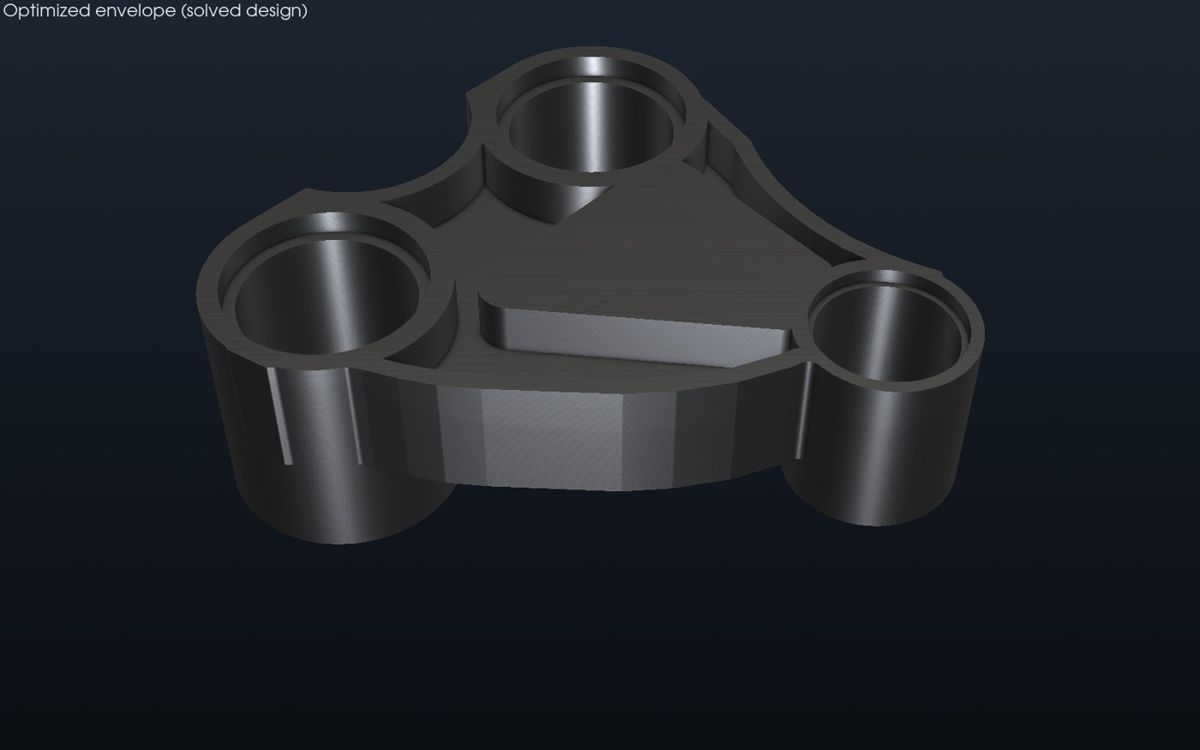
Every optimized part gets a slider. Drag it and the metal render slides into its stress heat map: blue = calm, red = working hardest. Same camera, same part, so you can see exactly where the load goes.
Included with Pro.
Now open to everyone
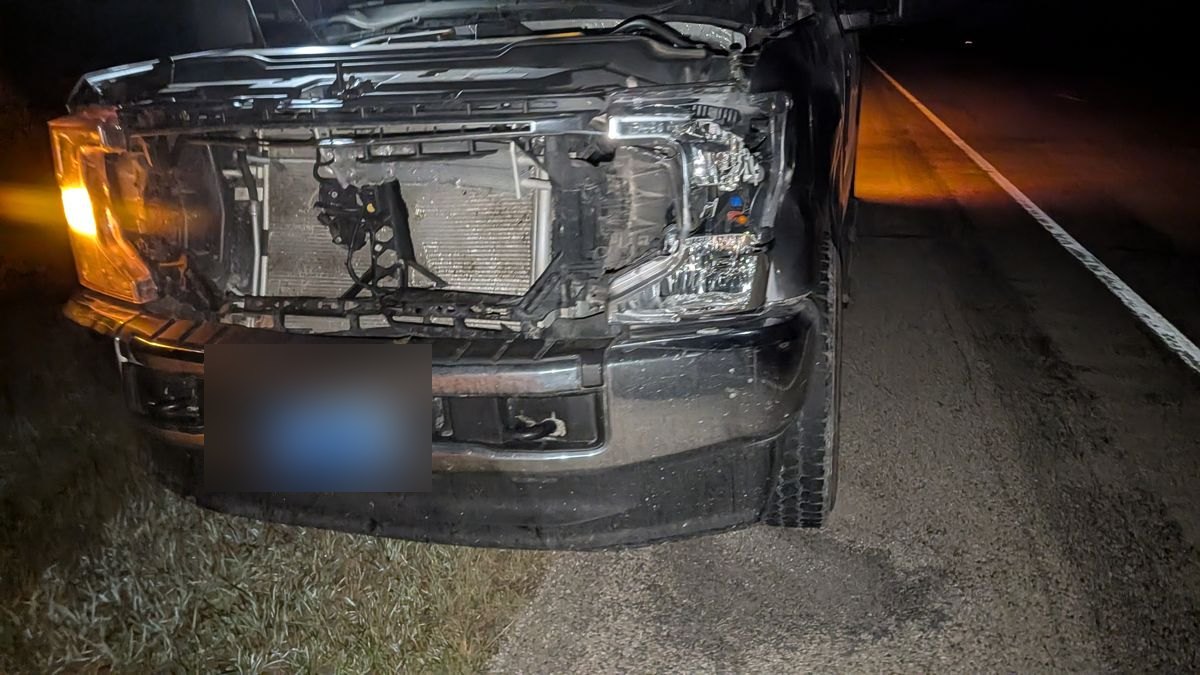
We built ScanIQ for days like the one the owner had in Montana: three elk, a wrecked F-250 front end, and a part that doesn't exist yet. Take phone photos of a part. Get back a measured 3-D model, a strength check you can read, a lighter version if you want one, and files to make it. Broken part? Rebuild it. Finished part? Put it on a product page.
For riders, moto shops, fabricators, small machine shops and restorers.
Real numbers from real jobs
Tags show where each number came from. See them all on Before & After.
Why we built this
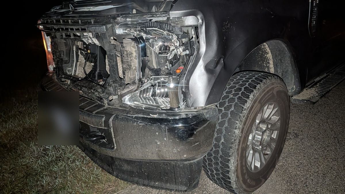
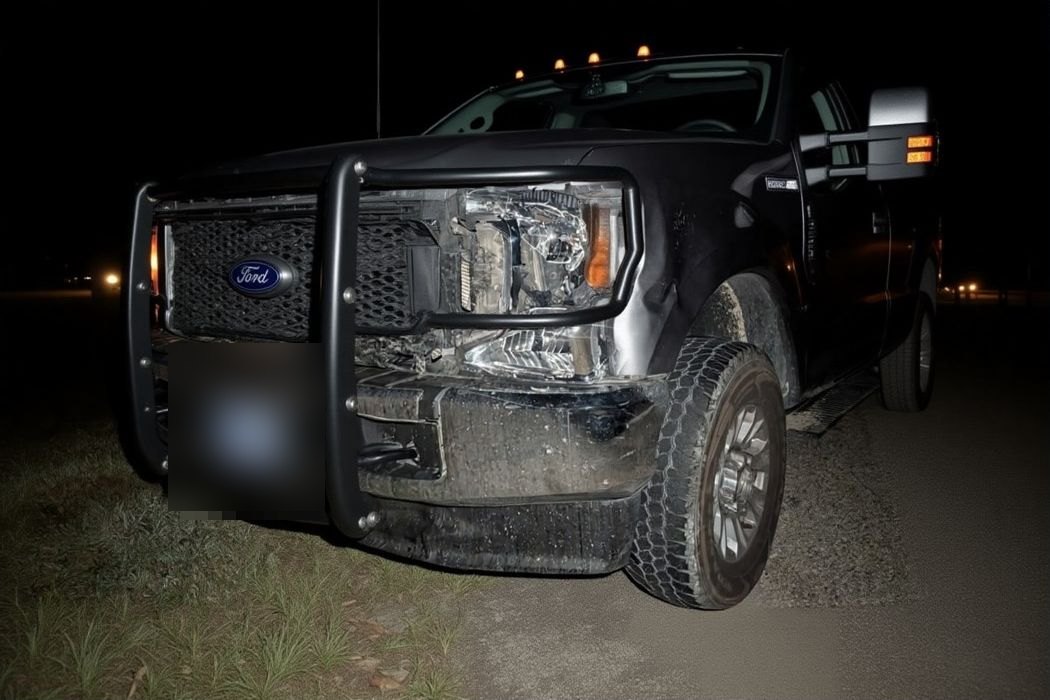
Just before sunrise on a Montana highway, the owner of ScanIQ hit three elk. They took out the front end of a 2021 F-250.
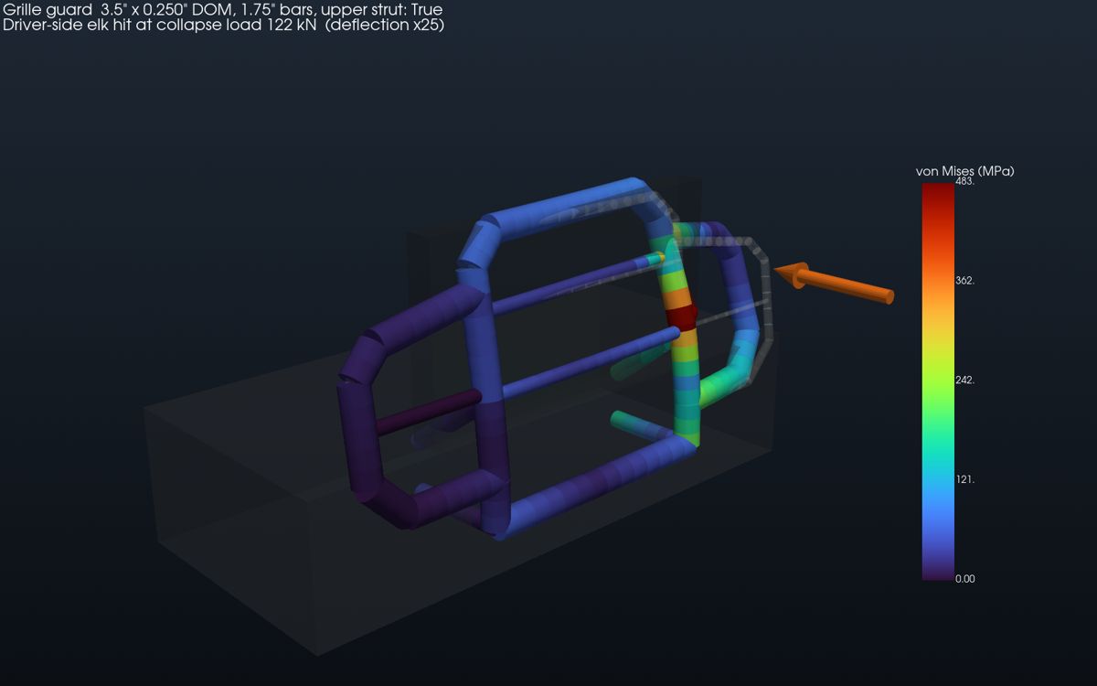
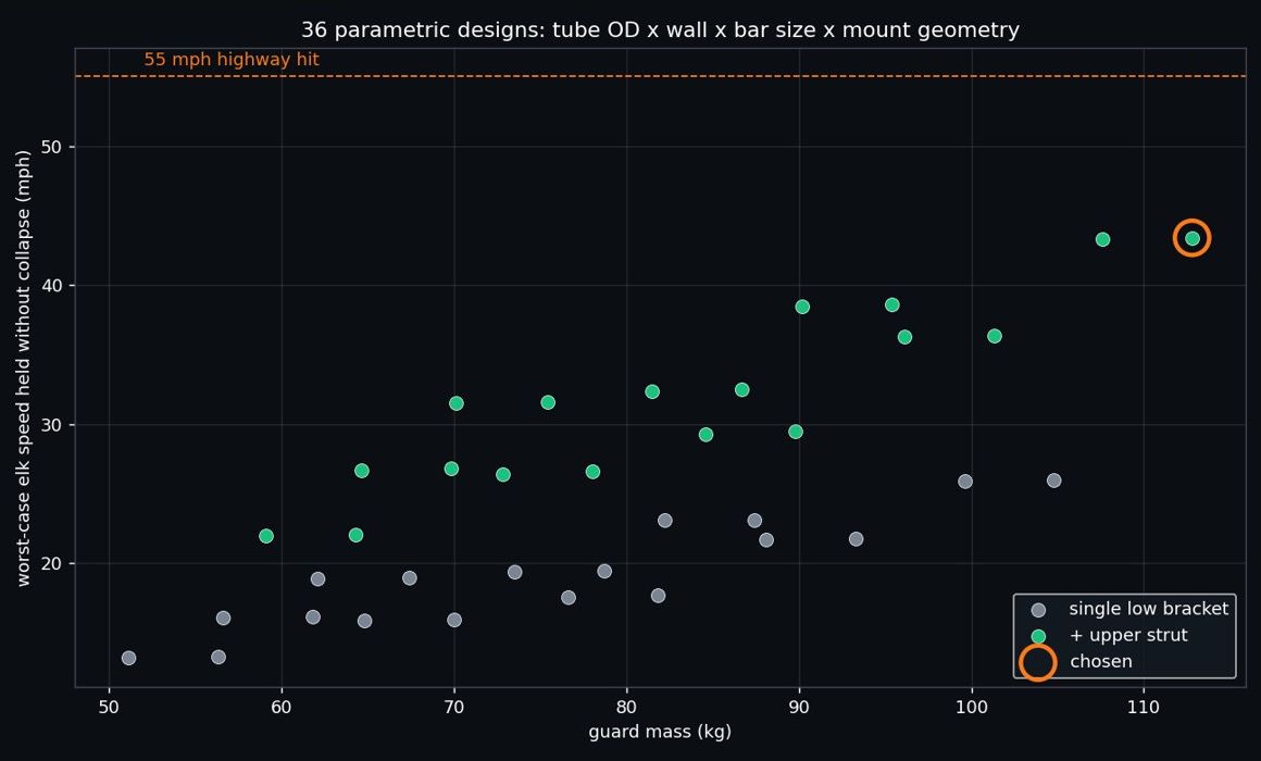
So we scanned the truck and used ScanIQ on our own problem. It designed a parametric grille guard: 3.5" × 0.250" DOM tube, 1.75" bars and upper struts, about 113 kg. Then it swept 36 designs by tube size, wall, bar size and mount geometry.
The chosen design holds a worst-case elk hit at about 43 mph without collapsing. The collapse load is 122 kN on a driver-side hit, where the stress peaks at the joint between the upright and the strut.
We are not done yet. The goal is a 55 mph highway hit, and no design in the sweep reaches it. These numbers come from a beam-theory solve with assumed dimensions [ASSUMED]. The guard has not been built or crash-tested.
New at launch
Every optimized part gets a slider. Drag it and the metal render slides into its stress heat map: blue = calm, red = working hardest. Same camera, same part, so you can see exactly where the load goes.
Included with Pro.
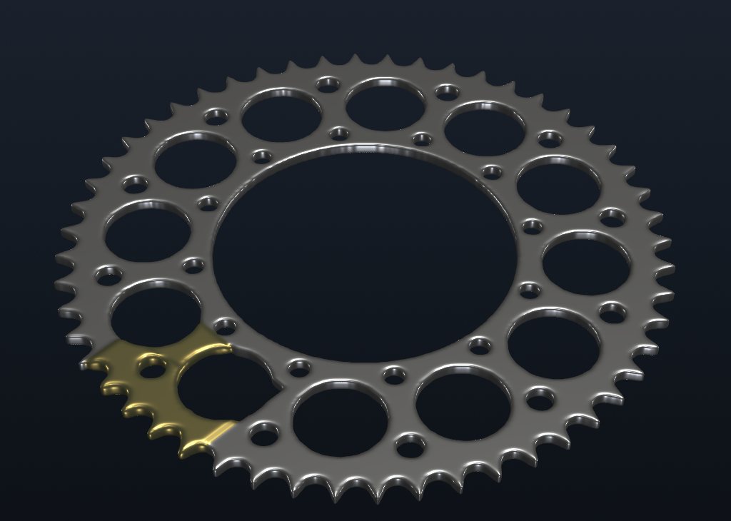
Got a chipped, cracked or broken part? Upload a scan or an STL. ScanIQ heals the geometry: it fills cracks and chips, and if the part is symmetric it rebuilds a missing side from the intact mirror side. The added material is highlighted in gold so you can see what changed, and you get back a printable STL.
Checking the strength of the healed part is a separate step. Run it before you trust the part.
Publish any finished part as a public product page: a 3-D viewer, renders, AI product images, a spec sheet and a Get one made button. AI images are labelled "Concept render (AI)" on the page.
Public links look like app.scaniq.online/p/your-part-name. Pro includes 5 listings.
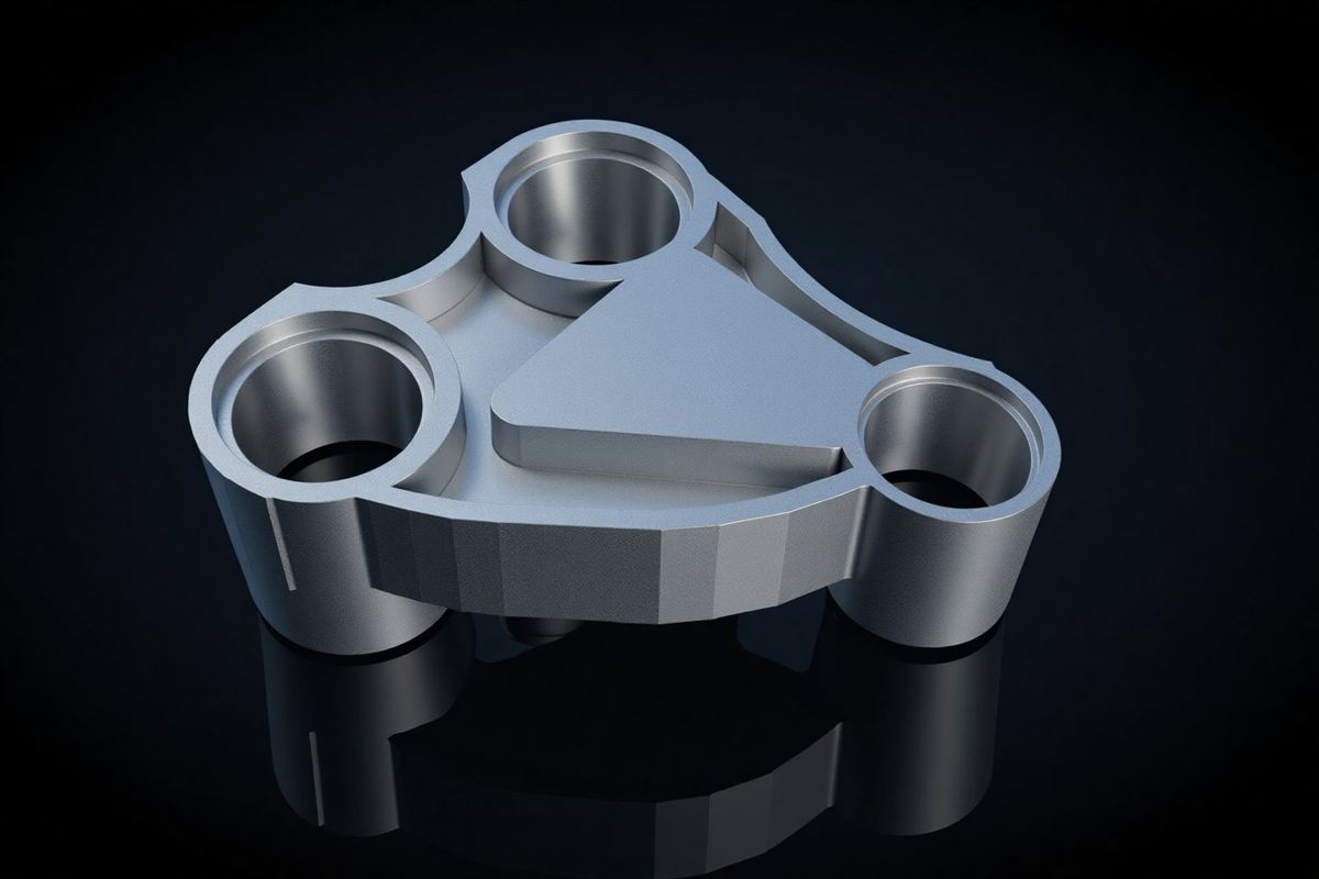
3-bore rocker linkage, optimized
Example listing layout. Sample loads are placeholders.
How it works
Walk around the part with your phone, with a ruler or the printed mat in the frame for true scale. The capture check scores your photos for blur and spacing in seconds, before you wait on a build. Already have an STL? Upload it.
Run the checks: strength (safety factor), vibration, fatigue and airflow. Every result is PASS, FAIL or INCONCLUSIVE, with a render you can open. Ask the Physics Coach what the numbers mean in plain words.
Optimize it lighter while it still meets the strength target, download files to print or machine, and publish it with Scan-to-Shelf if you want others to order one.
Before and after
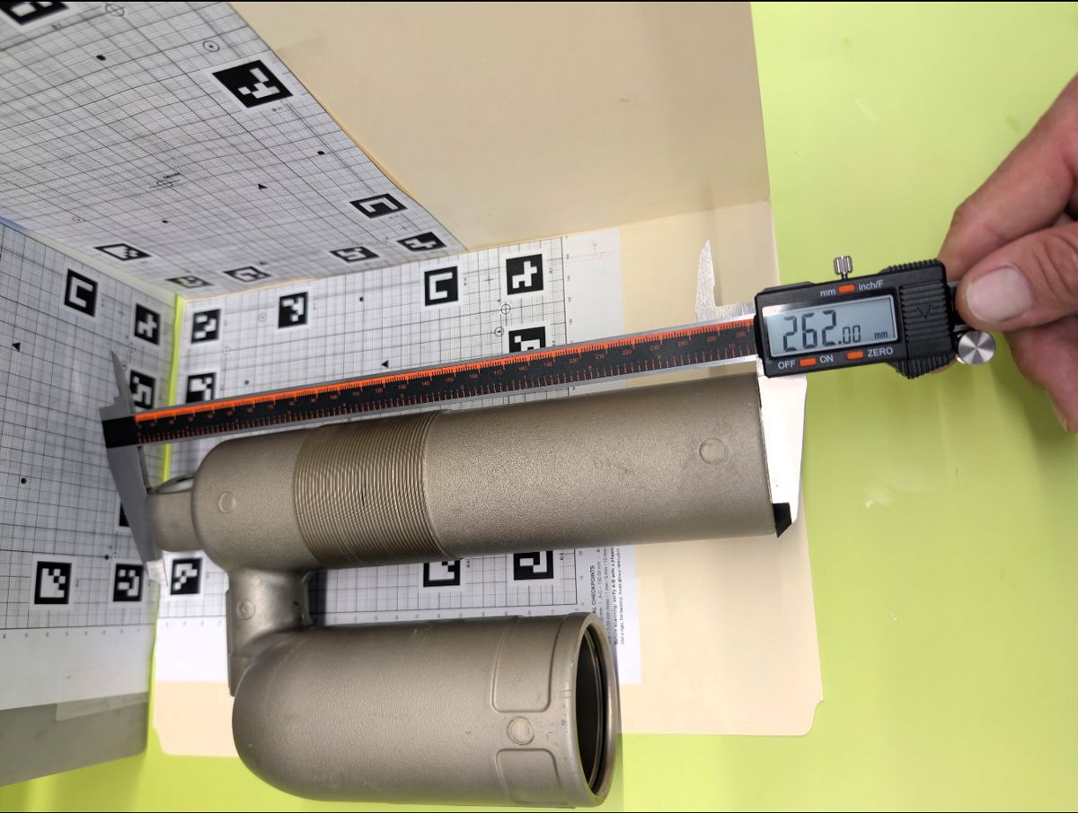
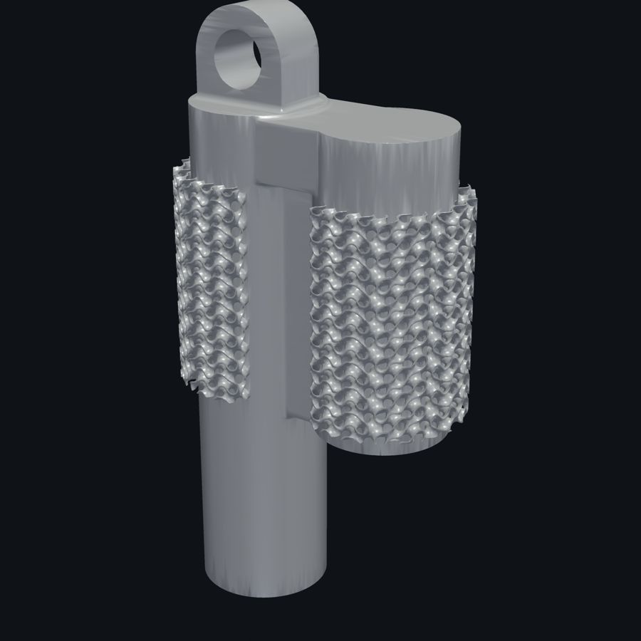
OEM shock body measured on the mat, then a new body with lattice sleeves on the body and reservoir.
262.00 mm by caliper
[CALIPER] · concept: generated, not built or flow-tested
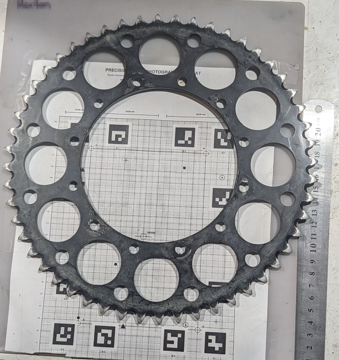
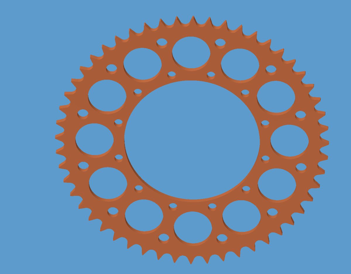
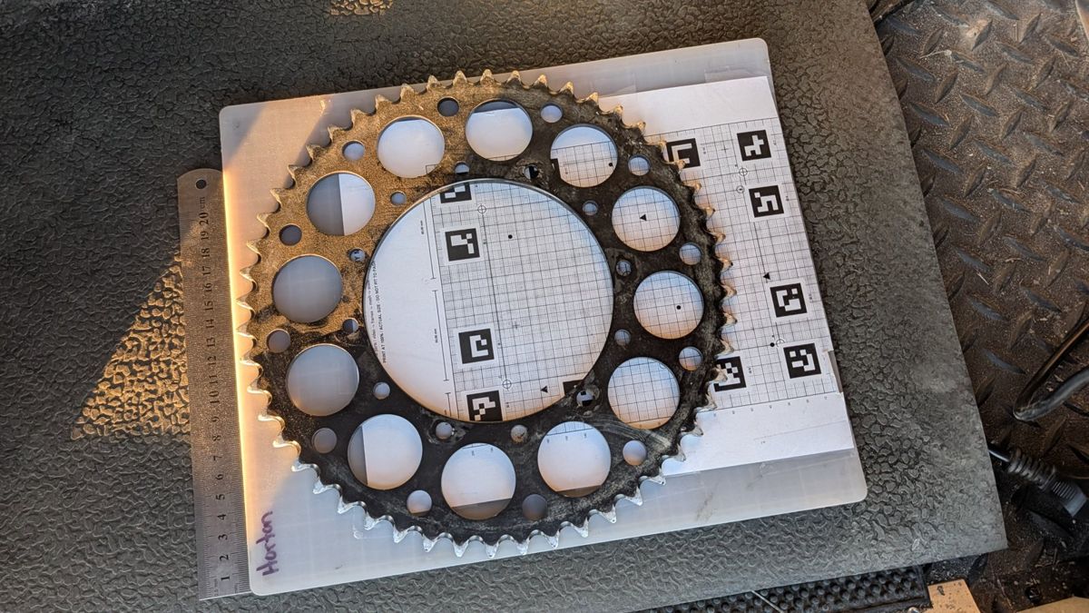
Sprocket on the mat with a ruler for scale, to an STL you can open on your phone.
261.05 mm by caliper
[CALIPER] · [PHOTO]
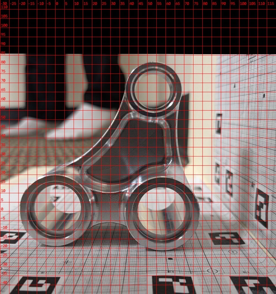
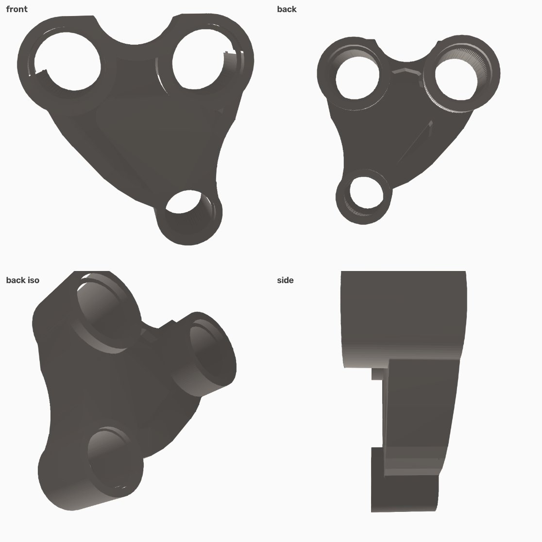
The original part was gone. One phone photo on the mat grid became a 3-bore model with a stress check.
[PHOTO] · some depths [ASSUMED]
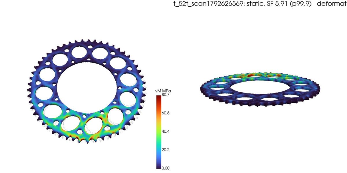
Phone photo on the mat to a measured parametric model and stress render.
SF 5.91
[PHOTO] · centre bore 136.65 mm by photo vs 133 mm by caliper, unresolved
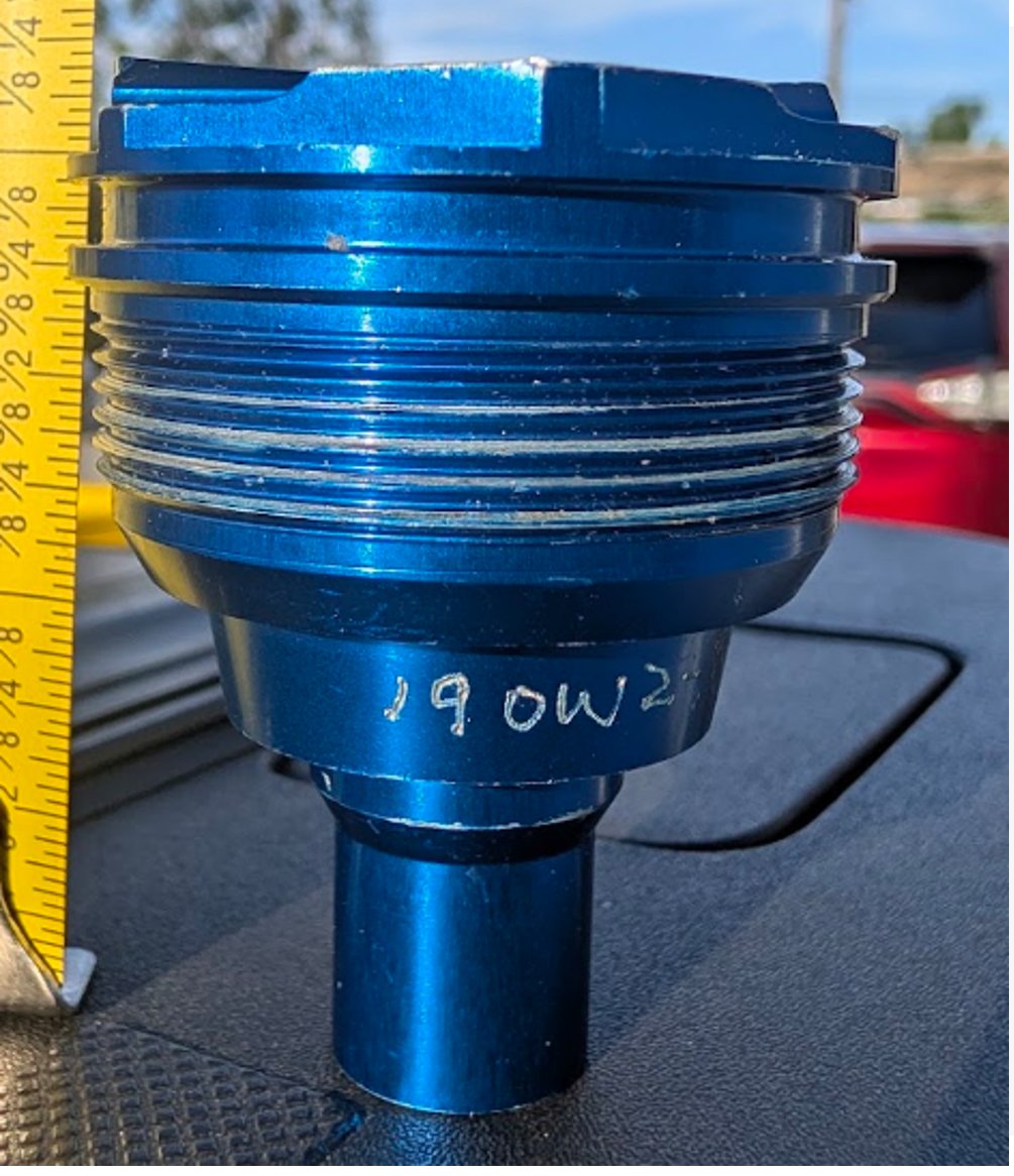
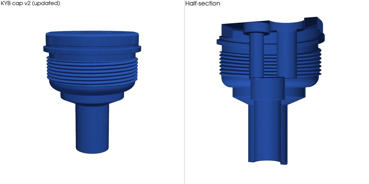
Photo of the original cap to a section model you can machine from.
Ø41.9 × 1.5 thread · stem OD 16 / ID 11 mm
[CALIPER] · [ASSUMED]
Pricing
$0
Most popular
$49/month
from $249
We take one part all the way for you. See the four options below and on the variations page.
Email to order| Option | From | What you get |
|---|---|---|
| Replicate | $249 | Watertight model of your part, same shape. Sample: 323.6 g. |
| Replicate + Style | $349 | Same outside, gyroid lattice inside. Sample: 249.9 g (concept). |
| Optimize | $499 | Solved lighter design that meets the strength target. Sample: 265.9 g. |
| Optimize + Style | $649 | Optimized, then the lattice on top. Sample: 206.2 g (concept). |
Questions
It depends on scale and capture. A ruler or the printed mat in the frame gives true scale, and the capture check catches blurry or badly spaced photos first. Every dimension is tagged with where it came from, and a measurement from photos alone can't get a PASS without a second check. We show it when sources disagree: on the KX250 sprocket the centre bore reads 136.65 mm from photos and 133 mm by caliper, and we list that as unresolved.
[CALIPER] means measured by hand with a caliper. [PHOTO] means measured from your photos. [ASSUMED] means an estimate that must be checked before you build. Lattice and generative designs are marked concept until they pass their own stress check.
You can use it to understand and plan the part, but treat the results as decision support. Engineering outputs are decision support. Safety-critical parts require qualified sign-off and physical testing. ScanIQ does not certify parts.
No. Ghost Parts rebuilds the shape and hands you a printable STL with the added material in gold. Strength is a separate check you run afterwards, and a safety-critical part still needs qualified sign-off and physical testing.
No. AI product images are made from the 3-D render for marketing and can change fine detail. They are always captioned "Concept render (AI)". Studio renders and stress maps come from the actual model.
A phone, decent light and a ruler or the printed mat. Keep the part still and move the phone around it. If you already have an STL, you can upload that instead.
A watertight STL you can send to a slicer, CAM or machinist, plus PNG renders. After a passing optimize run you also get the showcase pack: optimized STL, a gyroid-lattice STL (concept), studio renders and AI product images.
Email [email protected]. Refunds are covered on the refund policy page.
25 free jobs, no card. Scan something on your bench tonight.
Engineering outputs are decision support. Safety-critical parts require qualified sign-off and physical testing.